Digital troubleshooting
Back in the 1960s and 1970s, most electronic devices were manufactured with little automation. There was no robotic assembly to drive down the manufacturing cost. Component miniaturization had not gotten to the point where human repair became impractical. So, it was common to repair electronics equipment by troubleshooting down to the component level.
I worked for Tektronix in New York in the 1970s, starting out repairing equipment in their line of oscilloscopes and other test and lab instruments. When troubleshooting equipment based on analog circuitry, we used test equipment like oscilloscopes and multi-meters. Once you found the bad component, you'd unsolder it and solder in its replacement.
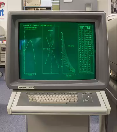
Tek introduced a line of graphics terminals based on storage tube technology (green-screen graphics). These terminals had quite a bit of digital logic circuitry, so when they broke and had to be repaired, troubleshooting with oscilloscopes and multi-meters no longer cut it.
I immediately volunteered to travel to company headquarters in Beaverton, Oregon to get up-to-speed on them. Convincing my boss was easy since I was already building my own microprocessor-based computers at home. I brought in one of my computers and used a program I wrote to display a graphic test pattern on the green screen of a salesman's demo unit. Both were impressed.
Logic probes
The graphics terminals were built using multiple circuit boards that plugged into a buss. Each board had a specific function so it wasn't normally difficult to know which board was malfunctioning. When a technician repaired a terminal in the field, he (there were only men doing this at first) replaced the board with a good one that he carried with him, thus fixing the customer's problem quickly. The bad board came back to the field service center where the manager could choose to send it back to the factory for repair or repair it locally.
If he chose to send it back to the factory, that would take a week or more. There had to be enough board inventory to cover the delay. There were dollar amounts tied to inventory and managers who kept their inventory low were considered better managers. My manager wanted to repair the boards locally.
The Tektronix service organization responded to the new logic-based products by recommending that field service centers acquire the Tektronix P6401 logic probe for technicians to use when troubleshooting logic circuits. The probe had red and green lights that would show the logic state. Both lights would blink when the probe touched a point that was toggling between states.
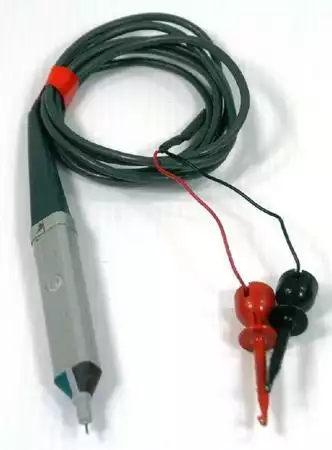
The probe was useful when a logic device was broken such that its output was stuck in one state, which was a common failure mode. You could fix about half of all broken logic boards with that simple tool. We fixed enough boards for Tek to declare us a board repair facility. We were repairing boards for our office and surrounding offices in New York, New Jersey, and western Connecticut.
However, logic probes could not fix a substantial number of broken boards. Sometimes an output was stuck because of a failure before the device–where the input conditions were wrong. You'd unsolder the chip and solder in a new one but didn't fix the board. A logic probe didn't help in many of these cases. Troubleshooting took much longer. You were replacing components that were not bad. Productivity suffered.
Logic analyzer
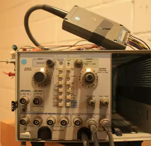
I managed to convince my manager, Dick, that troubleshooting digital circuitry required better digital tools. We needed a logic analyzer and Tektronix happened to make one–the LA-501 Logic Analyzer. I remember that he said he convinced his manager by saying that “Ed needed one”.
The LA-501 was a plug-in for a Tek TM-500 series chassis. It displayed its waveforms on an oscilloscope that was either another TM-500 plug-in or an external scope. I used an external scope. It provided a display similar to the one below. It could display 4, 8, or 16 traces. I was in heaven. If only my high school electronics teacher could see me now.
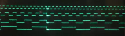
Now we could see the inputs and outputs for TTL devices and instantly see whether it was behaving correctly.
The Texas Instruments TTL Data Book for Design Engineers and its supplement were necessary adjunct tools when troubleshooting. It told you how the device was supposed to function and which pins the inputs and outputs were on.
For a time, I was the only one in the office who understood TTL logic, so we split the workload where I did the troubleshooting and a helper replaced the bad component. While the component was being replaced, I was troubleshooting the next board, Often, that helper was my manager, Dick, who I suspect wanted to be in on the cutting-edge of technology action. Sometimes, it was Bill Weiman, who will be discussed in another of my walks down memory lane.
A few weeks later, Dick hired another technician, named Dionne–born in Trinidad and studied electronics in southern Florida (Tampa, I think). At some point, Dionne tried to convince me that he knew logic by saying, “The output of a D flip-flop is what the input was before the clock pulse after the clock pulse.” That was good enough for me. He became a part-time troubleshooter; he had other primary duties.
Productivity
All repairs had service tickets attached, and labor hours had to be specified for every repair, so managers were able to track productivity. Apparently, our board repair center's productivity was much higher than the national average. We were getting talked about at national manager's meetings. I thought that was a good thing. I was naive.
My manager's manager arranged for me to visit other field board repair facilities as well as the repair facility at corporate office in Oregon. What I found helped explain why our productivity was much higher. Most of the technicians were using only logic probes and just checking for blinking lights. Some were also using cans of Freon because, sometimes "chips are heat sensitive". I remember joking, “Why not a flame thrower?”
One man did use a frequency counter and marked-up schematic diagrams, which was innovative. He had taken frequency measurements on a working board and annotated a schematic diagram of the board with those measurements. He had engineered a basic digital signature troubleshooting regime, which was the next evolutionary step beyond the simple logic probe. It also helped that frequency counters cost less than logic analyzers.
I don't remember his name so I'll refer to him as Gary. After I praised Gary for his clever solution, I told him about a similar technique I had proposed months earlier for troubleshooting analog circuits. Gary was surprised. “Analog?!” he asked/exclaimed. I showed him a drawing of a TM-500 plug-in I had proposed to a Tek engineering manager and dubbed the ASA-500, for Analog Signature Analyzer. Tek never built it, but they did build another of my proposals. That's another story.
The report
When my tour was over, my management expected me to write a report. I realized that, except for Gary, my findings were negative. My report suggested that Tek implement a strategy of education, the use of digital tools (praising Gary's innovation), and some computer assistance for exercising products under test, which I had developed. The result?
Within months, Tek corporate decided to shut down field board repair and have it all done at corporate office. Apparently, the managers of board repair centers that were on the low end of productivity revolted and national management saw this as a solution.
However, the visibility of our highly-productive repair facility helped earn my manager, Dick, a job at corporate office shortly after. Within months, he hired me. I moved to Oregon, where I became worldwide support for a range of products.